
Use Link Aggregation to increase bandwidth and redundancy between VigorSwitches
Link Aggregation is a method that helps to handle two or more physical links between two network devices. Owing to the combined links, the bandwidth between the Link Aggregation ports will break the speed limit of single Ethernet ports. Effectively associating the links between another switch or NAS supports Link aggregation, providing redundancy and improving performance. For example, two links will give you 2Gbps, three will give you 3Gbps, and so on.

Setting up Link Aggregation between two VigorSwitches
NOTE: To prevent the traffic loops, please do not cable more than one link before finishing the Link Aggregation configuration.
- VigorSwitches support OSI layer 2 and layer 3 aggregation:
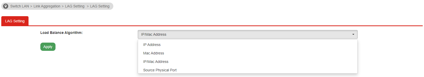
- "MAC Address" (OSI layer 2) which balances the traffic for different MAC addresses
- "IP & MAC Address" (OSI layers 2 & 3) balances traffic for different IP addresses or the MAC address.
Since firmware version 2.7.2, VigorSwitch 2280x and newer models support more options in Load Balance Algorithm:- "IP Address" which balances the traffic for different IP addresses
- "Source Physical Port" which balances the traffic for device connected in different physical port on VigorSwitch.
-
Navigate to Switch LAN >> Link Aggregation >> LAG Setting, we recommend selecting IP& MAC address for better compatibility and performance. Devices can share logical IP or MAC address and link the traffic, so the traffic which sends to the Internet, routers, and VPN will be aggregate together.
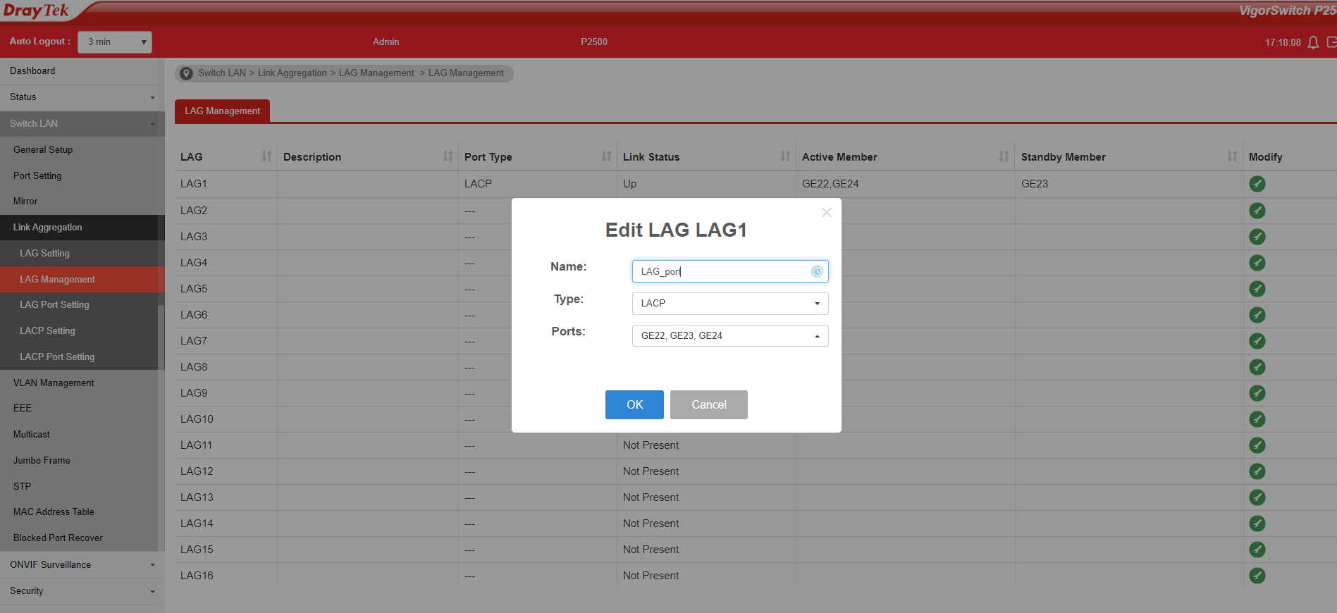
- Then navigate to Switch LAN >> Link Aggregation >> LAG Management, select a LAG port, and click the edit button.
- Select LAG port type, most of the devices support LACP. We recommend using LACP as Type. Because Static is binding the port without any protocols, if another side has the incorrect configuration, it may cause a network loop.
-
Add the port number into the Link Aggregation group.
-
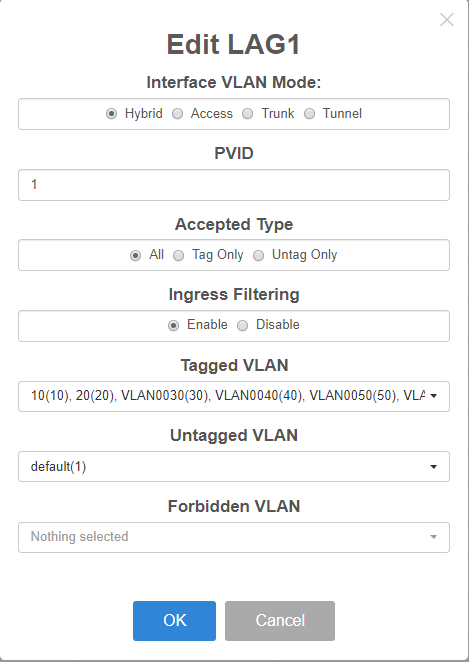
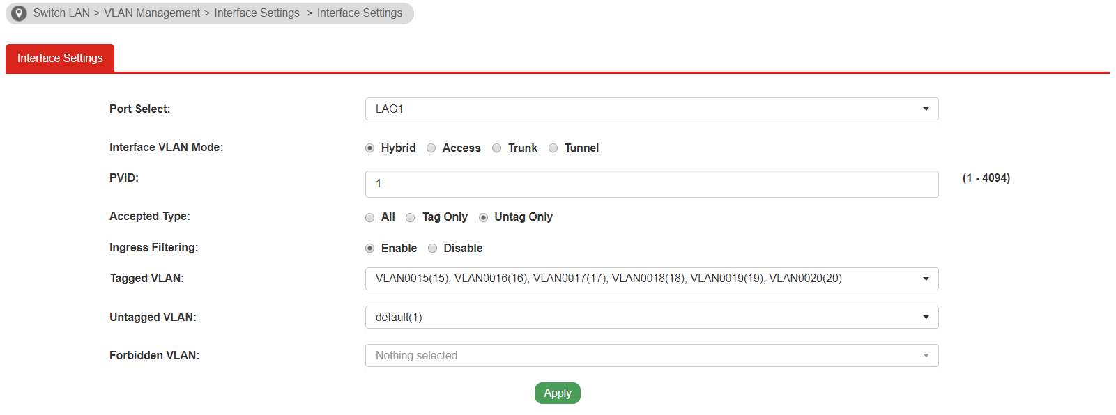
Assigning the correct VLAN for the LAG port by editing the configuration on the page of Switch LAN >> VLAN Management >> Interface Settings. VigorSwitch will identify the VLAN tag for the traffic in the LAG port.
- After the configuration above, wire multiple links to the LAG ports. The status will be displayed in Switch LAN >> Link Aggregation >> LAG Management. In these bundle links, the network traffic will automatically get adjusted and balanced for each connected device.
Troubleshooting
- If you found the LEDs on the LAG ports flash rapidly, it means the traffic loops in your switch, remove the link and check the configuration of Link aggregation again.
- Some packet losses: Check the VLAN configuration of your LAG port, make sure your connected device is getting the correct IP.
Published On:2019-10-07
ShareWas this helpful?