
How to send all the traffic to VPN tunnel on Vigor3900/2960
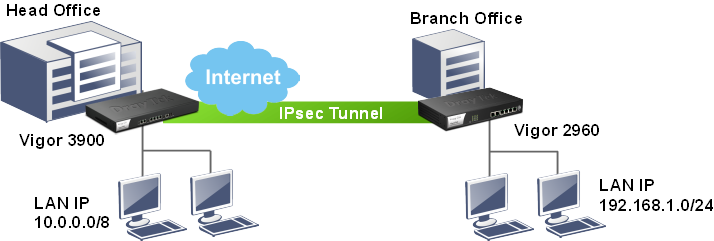
Assuming Vigor3900 is in the head office and Vigor2960 is in the branch office, the network Administrator wants to create a VPN between the two offices and make Vigor2960 to send all traffics to this VPN tunnel. The examples below will show you two ways to achieve this purpose.
A. GRE over IPsec + Route Policy
Configurations on Vigor3900 in the head office
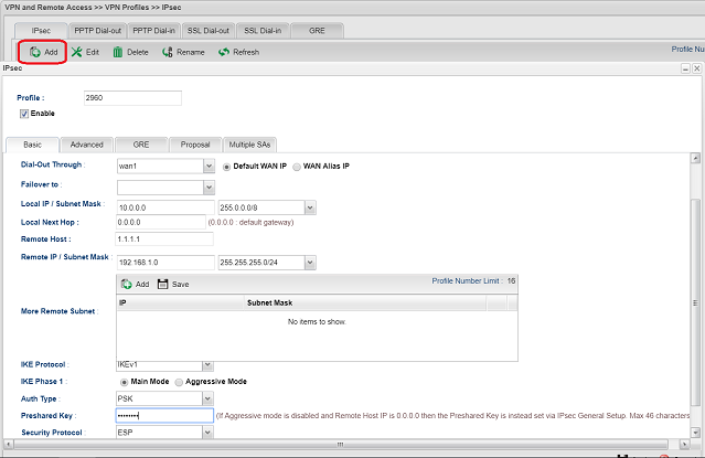
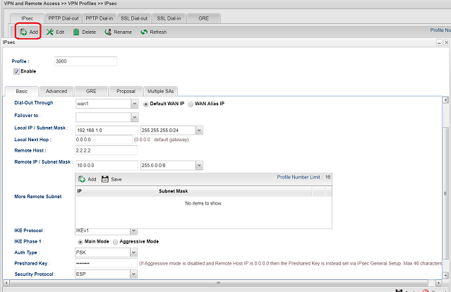
1. Add a new VPN profile: Go to VPN and Remote Access >> VPN Profiles, click Add and configure Basic Settings:
- Check Enable.
- Input Local IP/ Sub net as 10.0.0.0/8.
- Input Remote Host as Vigor2960's WAN IP.
- Input Remote IP/ Subnet as Vigor2960's LAN IP.
- Select Main Mode for IKE Phase1.
- Input Preshared key.
- Select ESP for Security Protocol.
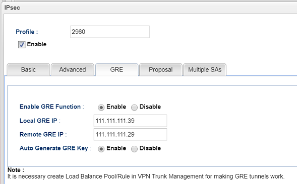
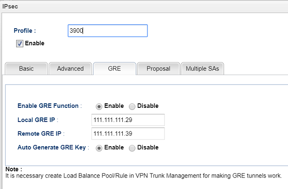
2. Configure GRE Settings for the VPN profile.
- Enable GRE function.
- Input Local GRE IP (It should be the same as the Remote GRE IP on the Vigor2960 in the branch office)
- Input Remote GRE IP (It should be the same as the Local GRE IP on the Vigor2960 in the branch office)
- Apply the settings.
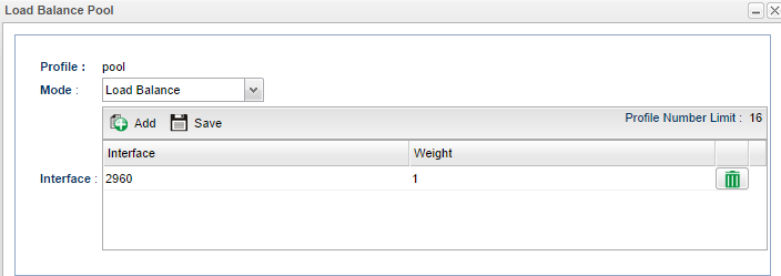
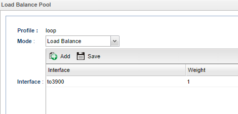
3. Create a VPN Load Balance Pool: Go to VPN and Remote Access >> VPN Trunk Management >> Load Balance Pool, then click Add to create a new one.
- Input Profile Name.
- Click Add to select the VPN profile we just created and give the Weight (Only the VPN profile with GRE setting will be listed here.)
- Apply the settings
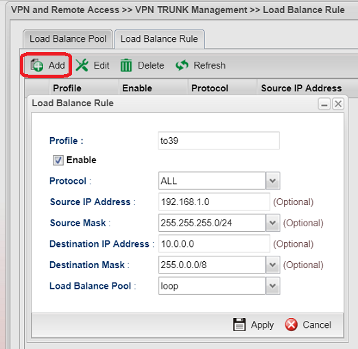
4. Create a VPN Load Balance Rule: Go to VPN and Remote Access >> VPN Trunk Management >> Load Balance Rule, then click Add to create a new one.
- Input Profile Name.
- Select ALL for Protocol.
- Input Source IP Address
- Input Source Mask
- Input Destination IP Address
- Input Destination Mask
- Select the VPN Trunk Load Balance Pool for Load Balance Pool.
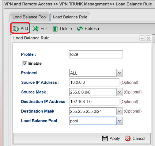
Note: It is necessary to define what kind of traffic needs to go through the VPN Trunk tunnel with VPN Load Balance Rule. Otherwise, the traffic won't pass to the VPN Trunk tunnel.
Configurations on Vigor2960 in the branch office
1. Add a new VPN profile: Go to VPN and Remote Access >> VPN Profiles, click Add and configure Basic Settings:
- Check Enable.
- Enable Auto Dial-Out and select Always Dial-Out.
- Input local IP/ Subnet as 192.168.1.0/ 255.255.255.0
- Input Remote Host IP as Vigor3900's WAN IP
- Input Remote IP/ Subnet as 10.0.0.0/ 255.0.0.0
- Select Main Mode for IKE Phase1
- Input Preshared key
- Select ESP for Security Protocol
2. Configure GRE Settings or the VPN profile:
- Check Enable to Enable GRE function.
- Input Local GRE IP (It should be the same as the Remote GRE IP on the Vigor3900 in the head office)
- Input Remote GRE IP (It should be the same as the Local GRE IP on the Vigor3900 in the head office)
- Apply the settings.
3. Create a VPN Load Balance Pool: Go to VPN and Remote Access >> VPN Trunk Management >>Load Balance Pool, then click Add to create a new one.
- Input Profile Name.
- Click Add to select the VPN profile we just created and give the Weight (Only the VPN profile with GRE setting will be listed here.)
- Apply the settings.
4. Create a VPN Load Balance Rule: Go to VPN and Remote Access >> VPN Trunk Management >> Load Balance Rule, then click Add to create a new one.
- Input Profile Name.
- Select ALL for Protocol.
- Input Source IP Address
- Input Source Mask
- Input Destination IP Address
- Input Destination Mask
- Select the VPN Trunk Load Balance Pool for Load Balance Pool.
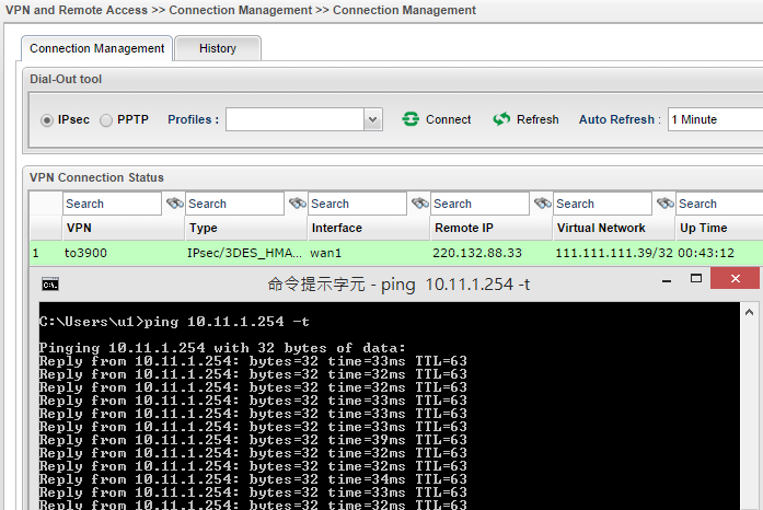
5. After completing the configurations above, the VPN tunnel should be dialed up now. Go to VPN and Remote Access >> Connection Management for checking its status. Furthermore, ping to confirm if a local computer can get a ping response from a remote computer.
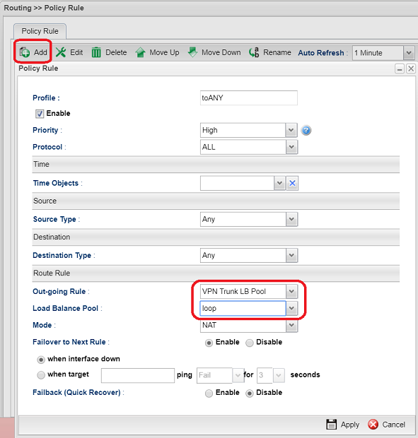
6. Create a Policy Rule to force all the traffics to go through the VPN Trunk Tunnel: Go to Routing>> Policy Route then click Add to add a new rule.
- Input Profile Name
- Check Enable
- Select ALL for Protocol
- Select ANY for Source Type
- Select ANY for Destination Type
- Select VPN Trunk LB Pool for Out-going Rule
- Select the VPN Load Balance Profile for Load Balance Pool.
- Select NAT for Mode
- Apply the settings.
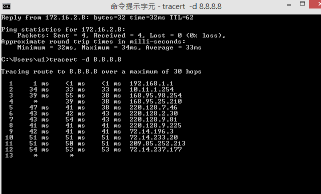
7. Using traceroute command “tracert -d” to confirm if all the traffics are going through the VPN tunnel. From the traceroute result in the below screenshot, we can see the second node is Vigor3900's LAN IP and that means the traffic to 8.8.8.8 is sending through the VPN tunnel.
B. NAT Policy
Configurations on Vigor2960 in the branch office
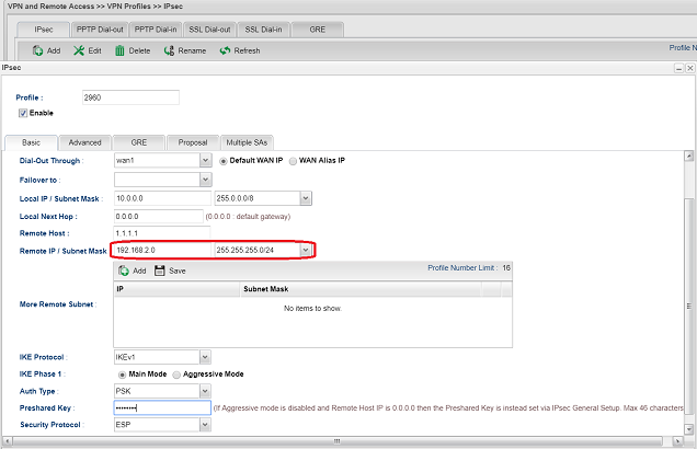
1. Add a new VPN profile: Go to VPN and Remote Access >> VPN Profiles, click Add and configure Basic Settings:
- Check Enable.
- Enable Auto Dial-Out and select Always Dial-Out.
- Input local IP/ Subnet as 192.168.1.0/ 255.255.255.0
- Input Remote Host IP as Vigor3900's WAN IP
- Input Remote IP/ Subnet as 10.0.0.0/ 255.0.0.0
- Select Main Mode for IKE Phase1
- Input Preshared key
- Select ESP for Security Protocol
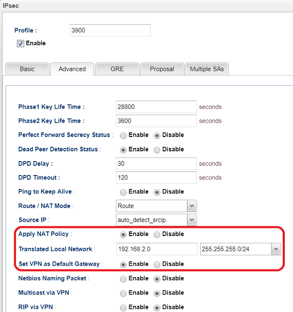
2. Enable Apply NAT policy in Advance tab
- Enter a network to translate 2960's LAN for the interface to send all traffic to
- Enable Set VPN as Default Gateway
Configurations on Vigor3900 in the head office
1. Add a new VPN profile: Go to VPN and Remote Access >> VPN Profiles, click Add and configure Basic Settings:
- Check Enable.
- Input Local IP/ Sub net as 10.0.0.0/8.
- Input Remote Host as Vigor2960's WAN IP.
- Input Remote IP/ Subnet as Vigor2960's translated network IP.
- Select Main Mode for IKE Phase1.
- Input Preshared key.
- Select ESP for Security Protocol.
2. Using traceroute command “tracert -d” to confirm if all the traffics are going through the VPN tunnel. From the traceroute result in the below screenshot, we can see the second node is Vigor3900's LAN IP and that means the traffic to 8.8.8.8 is sending through the VPN tunnel.
Published On:2019-07-16
ShareWas this helpful?