
Three-Site VPN Communication
It is common that a company has a headquarter and few branches locate at different places. The network administrator can establish a VPN tunnel between hear quarter and each branch, so the employees on the branch site can access the service and resource in headquarter. The network administrator can also establish the VPN tunnel between the branch sites, so the employee can access to each other on the different branches. However, this is only an easy job for network administrator when there are only a few branches.
Let do some simple calculations, how many VPN tunnels should network administrator constructs, in order to let the employees access each site's service and resource? If there are three sites, the network administrator will need to construct three tunnels; if there are four sites, they will need six tunnels. Five sites, ten tunnels. If we have n sites, then we will need Ʃ(n-1) tunnels. It will become not an easy job for the network administrator to handle this amount of VPN tunnels.
To make the task easier, the network administrator can construct the VPN tunnels between each branch and headquarter, then let the headquarter forward the traffic from one branch to another. So, the network administrator will only need to construct and maintain lesser VPN tunnels which the amount is as same as the branch offices.
This article introduces how to create a LAN to LAN multiple VPN clients using IPSec, and to let the branch offices communicate with each other through Following is the scenario.
Vigor Router in headquarter will be the VPN server (dial-in site), both Vigor Routers in the branch office will be the VPN clients (dial-out sites).
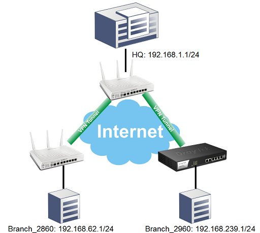
VPN configuration on Vigor Router in HQ
Go to VPN and Remote Access >> IPsec General Setup, and enter the PSK (PreShared Key)
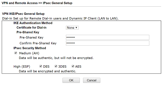
Configuration on HQ VPN server for Branch_2960
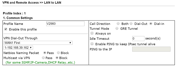
Go to VPN and Remote Access >> LAN to LAN, and click an available index
In Common Settings:
- Check Enable this profile.
- Select Call Direction as "Dial-In".
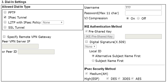
In Dial-In Settings:
3. Select the IPSec Tunnel service.
In TCP/IP Network Settings:
4. Enter the LAN IP and Subnet Mask of the remote side in Remote Network IP and Mask.
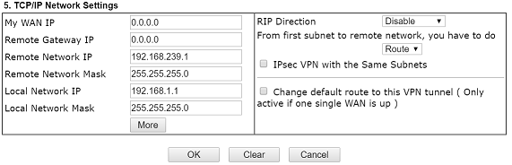
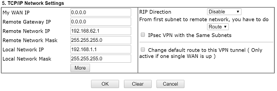
Configuration on HQ VPN server for Branch_2860
Similar to configuration for branch_2960, only need to change remote network to LAN of Vigor2860.
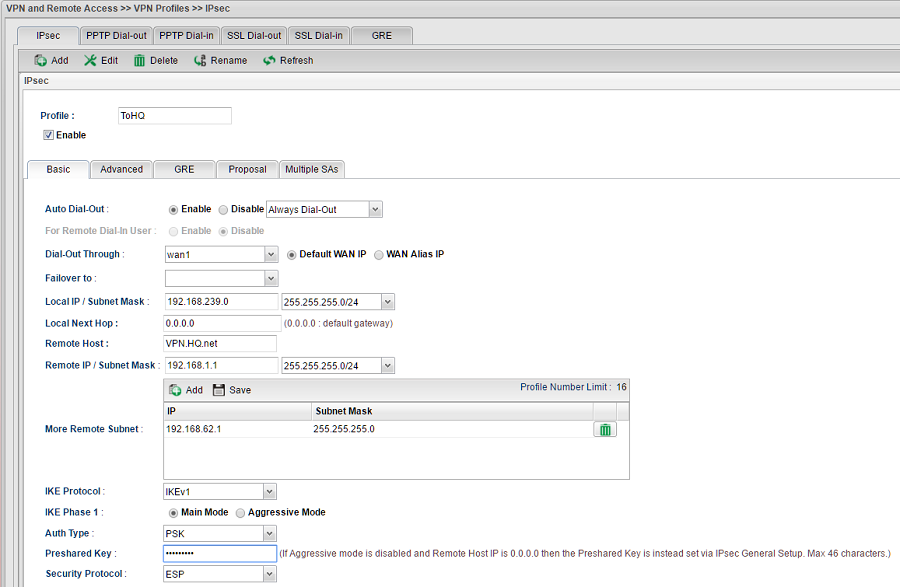
VPN configuration on Branch_2960
Go to VPN and Remote Access >> VPN Profiles.
- Click Add to create a new IPsec VPN Profile.
- Enable the profile and set the name
- Input Vigor2960's LAN IP and Subnet Mask as Local IP/ Subnet Mask.
- Input the WAN IP/Domain of VPN server as Remote Host.
- Input the LAN IP and Subnet Mask of VPN server as Remote IP/Subnet Mask.
- Input the LAN IP and Subnet Mask of Branch_2860 in More Remote Subnet.
- Input the Preshared Key.
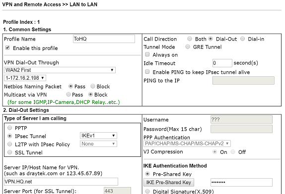
VPN configuration on Branch_2860
Go to VPN and Remote Access >> LAN to LAN, and click an available index
In Common Settings:
- Check Enable this profile.
- Select Call Direction as "Dial-Out".
In Dial-Out Settings:
- Select the IPSec Tunnel service.
- Set the Server's WAN IP/Domain of the remote side.
- Click "IKE Pre-Shared Key" and enter the preshared key.

In TCP/IP Network Settings:
- Enter the LAN IP of the remote site in Remote Network IP
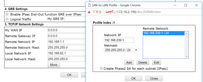
- The "More Route" function allows more connections with other branch offices through the VPN server in head quarter. To activate it, please click "More" and follow the setting below.
- Set the LAN IP address and Subnet Mask of the other branch office.
- Click Add to add it to the Remote Network.
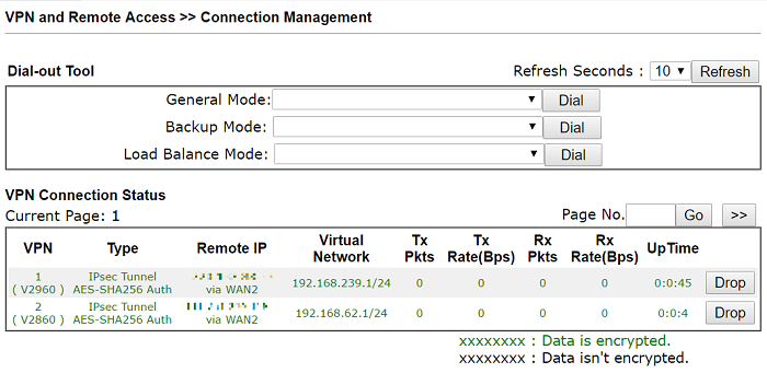
Once the IPSec tunnel is established between all three devices, you can check the tunnel status under Connection Management of each device. You can also use the Ping Tool under Diagnostics to check if you can ping the remote site.
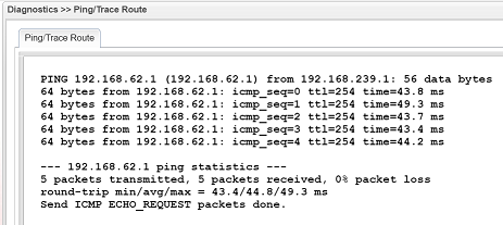
Now the branch offices should be able to reach mutually through the Vigor router in head quarter.
Ping from Branch_2960 to Branch_2860
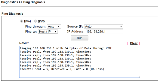
Ping from Branch_2860 to Branch_2960:
Many organizations have a headquarters (HQ) and several branch offices distributed across different locations. To ensure secure connectivity and resource sharing between all sites, VPN tunnels are typically deployed.
Scenario
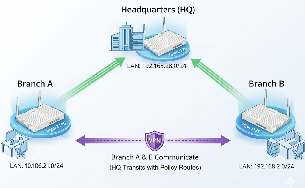
- Headquarters (HQ)
LAN: 192.168.28.0/24
Role: VPN Server (Dial-in) - Branch A
LAN: 10.106.21.0/24
Role: VPN Client (Dial-out) - Branch B
LAN: 192.168.2.0/24
Role: VPN Client (Dial-out)
Objective
- Branch A can access HQ resources
- Branch B can access HQ resources
- Branch A and Branch B can communicate with each other
Instead of creating VPN tunnels between every site, the network administrator only establishes:
- One VPN tunnel between HQ and Branch A
- One VPN tunnel between HQ and Branch B
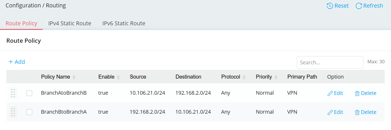
The HQ router then creates Policy Route rules to forward traffic between Branch A and Branch B.
In this setup, one Vigor2136 at HQ acts as the VPN server, and the other two Vigor2136 at the branch offices act as VPN clients. All inter-branch traffic passes through HQ.
VPN Configuration on Vigor Router – Headquarters (HQ)
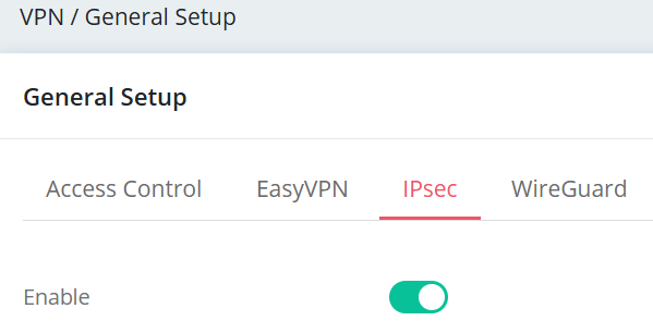
1. Enable IPsec VPN Service
Navigate to VPN / General Setup / IPsec, toggle Enable, then Apply the setting.
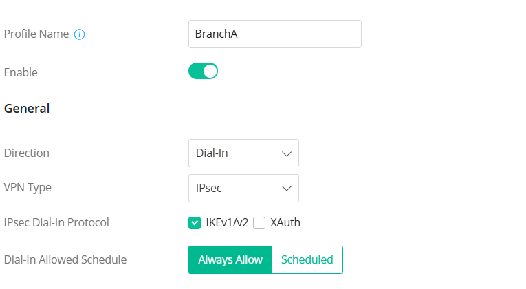
2. Create IPsec Site to Site VPN profiles for Branch A.
Navigate to VPN / Site to Site VPN, click +Add.
Under General
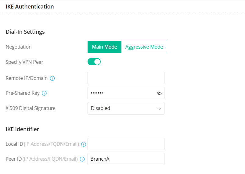
Under IKE Authentication
Under Network
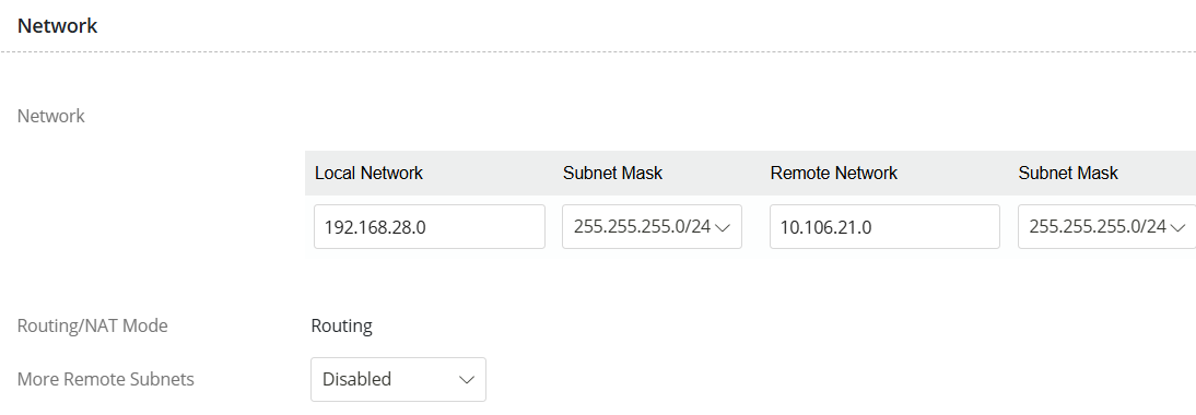
3. Similarly, create IPsec Site to Site VPN profiles for Branch B.
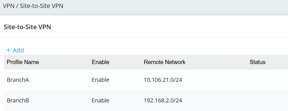
4. Add Route Policy rules.
Navigate to Configuration / Routing. Click +Add to create the Route Policy rules.
VPN Configuration on Vigor Router – Branch Office A
1. Enable IPsec VPN Service
Navigate to VPN / General Setup / IPsec, toggle Enable, then Apply the setting.
2. Create IPsec Site-to-Site VPN Profile to HQ.
Navigate to VPN / Site to Site VPN, then click +Add.
Under General
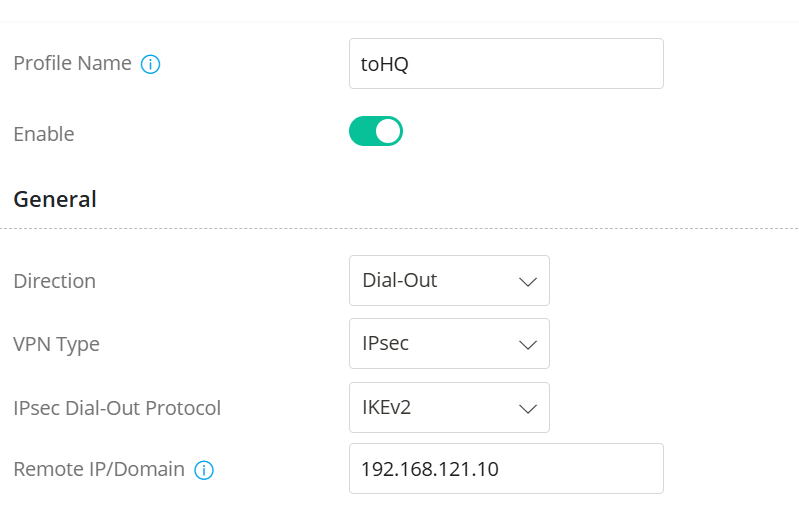
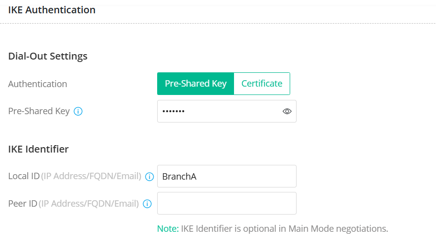
Under IKE Authentication
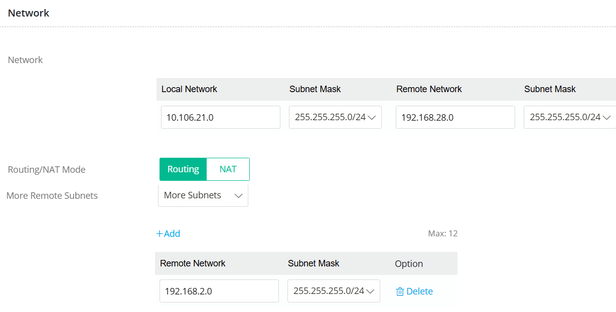
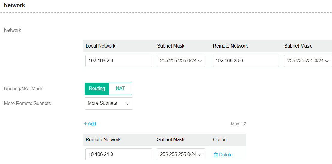
Under Network
VPN Configuration on Vigor Router – Branch Office B
1. Enable IPsec VPN Service
Navigate to VPN / General Setup / IPsec, toggle Enable, then Apply the setting.
2. Create IPsec Site-to-Site VPN Profile to HQ.
Navigate to VPN / Site to Site VPN, then click +Add.
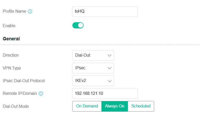
Under General
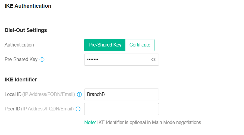
Under IKE Authentication
Under Network
Verify the VPN connection
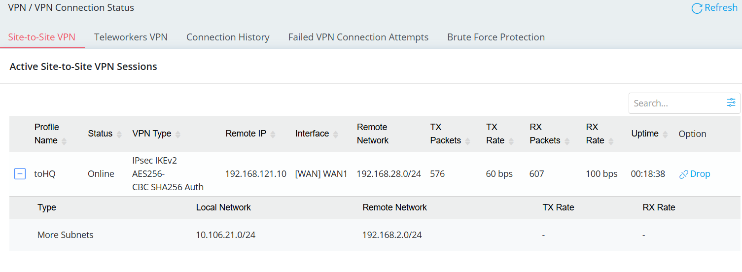
1. Navigate to VPN → VPN Connection Status to check if the VPN is up.
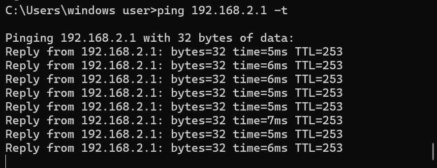
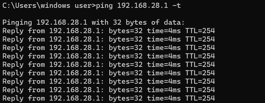
2. Use Ping to verify connectivity to both the HQ and the remote branch office.
Published On:2026-03-12
ShareWas this helpful?